A private hobbyist website
with focus on CNC, electronics and software.
![]()
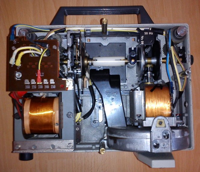
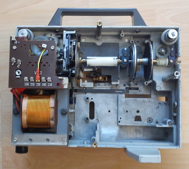
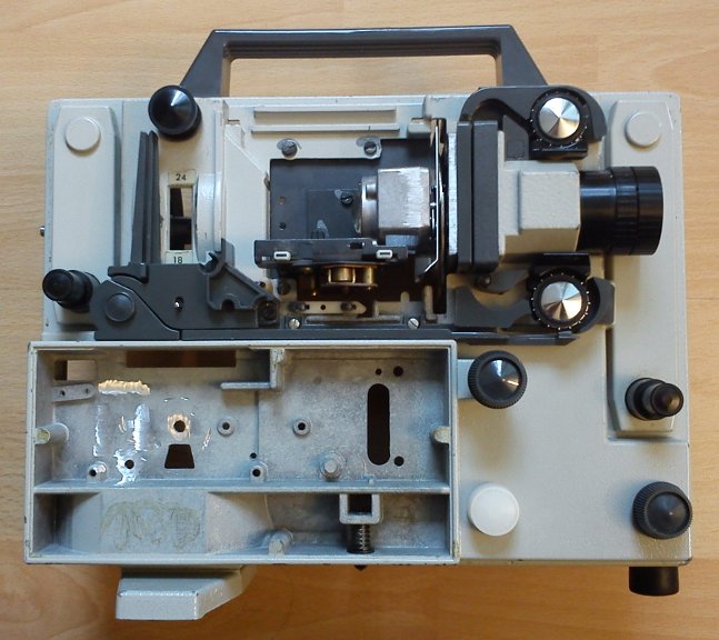
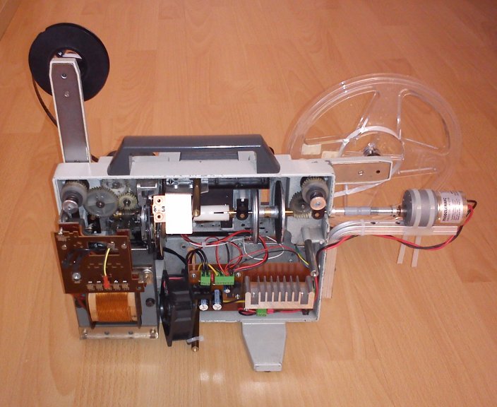
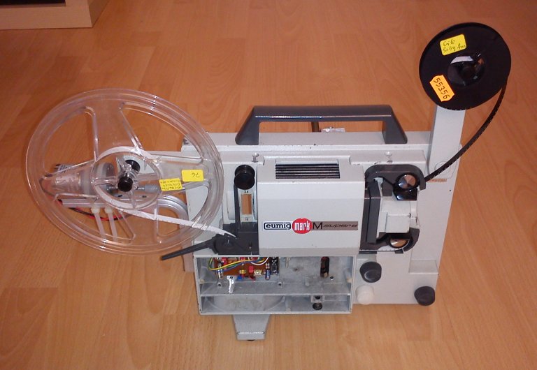
Super8 telecine machine (under work)
This is my DIY Super8 telecine project. Until completion enjoy the picture gallery.
Key parts
- Super8 projector: EUMIG Mark M
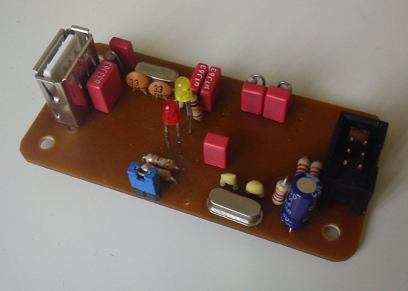
- Microcontroller: Renesas R8C13
- USB/Serial converter: Microchip MCP2200
- Motordriver: L6203
- Motor: RB-35 (geared motor, 12V, 52 RPM, 180Ncm)
Picture gallery
Downloads
- Schematics power supply (PDF)
- Schematics motor h-bridge (PDF)
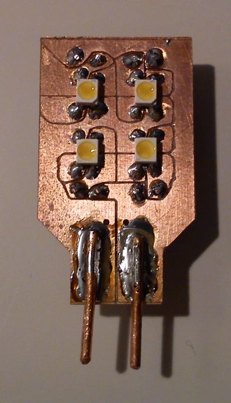
- Schematics led light source (PDF)
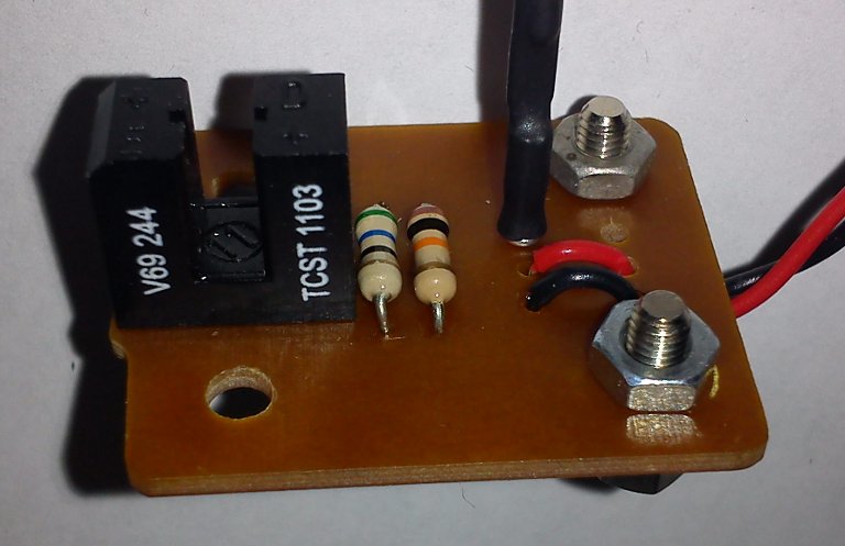
- Schematics shutter sensor (PDF)
- Schematics microcontroller board (PDF)
Publish date: 2013-05-31
Last update: 2013-06-02
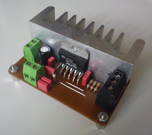
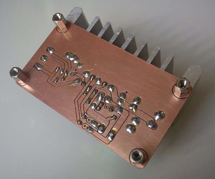
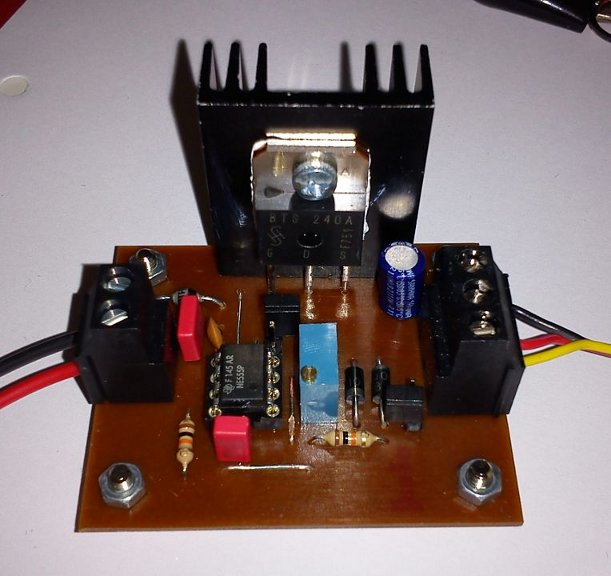
PWM module
This is a small pwm module with a fixed frequency and manually adjustable ratio. I used it to control the speed/torque of a small 6V motor. Works fine.
The main parts are a NE555 timer ic and a fet, so nothing special. Remark: The heatsink in the picture might not be sufficient for all applications.
The frequency is set to about 14kHz (due to the parts I had available). Change RV101 and C102 to your needs. Formula: f=SQRT(2)/(RV101*C102).
Download
- Schematics (PDF)
Publish date: 2012-07-19
![]()
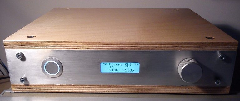
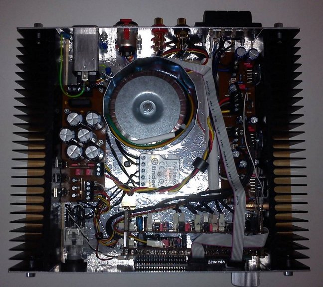
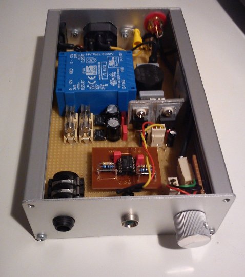
Analog 2.1 amplifier
This is my little multimedia amp used in conjunction with two PCs. It is also my first DIY amplifier project. The amp currently drives two DIY satellite speakers (8 Ohm) based on the Visaton NANO SAT MK II design and one 12" Axton subwoofer (4 Ohm) in a DIY closed 30 l cabinet. Any constructive feedback is very welcome!
Features
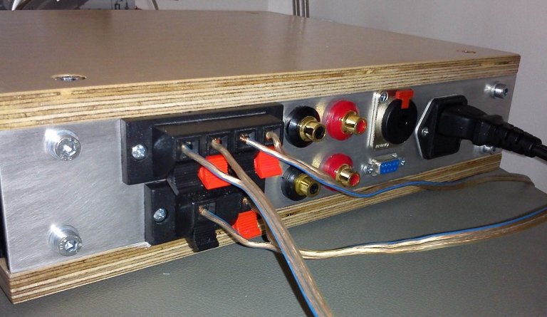
- Inputs: 2x stereo line-in with controllable attenuation.
- Outputs: 3x speaker (4-8 Ohms). Left, Right, Sub-Woofer. 1x headphone.
- Mixing of the two stereo inputs.
- Controllable low pass filter (Fcut: ~40-160 Hz) and attenuation for the sub-woofer.
- Electronic potentiometers instead of mechanical ones.
- Push-button rotary encoder for user input.
- 3x16 character display.
- Mains voltage: 230VAC.
- Power consumption: ~15 W.
- Key parts: LM3886T, OPA2134, MCP42010, R8C13, EA DOGM163.
- Dimensions: L = 250 mm, W = 300 mm, H = 80 mm.
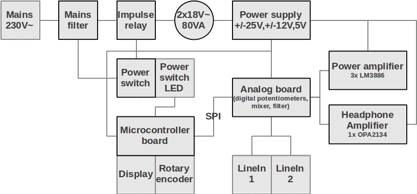
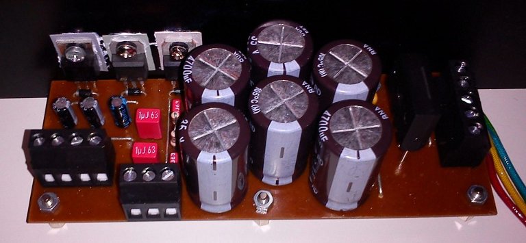
Power supply
Features
- +25V, GND, -25V for power amp.
- +12V, GND, -12V for op amps.
- +5V, GND for micro, display, LEDs, potentiometers and mute function.
- Energised by a 80VA 2x18V toroid transformer.
- Design based on National Semiconductor AN-1849 (An Audio Amplifier Power Supply Design).
Review
- ~14mF per rail provide sufficient filtering.
- A 1/4 W snubber resistor is enough (R102, R103).
- Standard components seem sufficient.
- Connection to chassis ground does show any difference (P101).
- The 80VA transformer "sees" a mean load of ~15W typically.
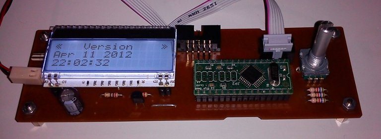
Microcontroller board
Features
- Renesas R8C13 microcontroller (Ram 1K, Flash 16k, Data-Flash 4k).
- EA-DOGM163W-A display.
- EA LED55X31-W back-light.
- Rotary encoder with push-button.
- Switch-able power button led output.
- Switch-able display back-light.
Review
- No noise counter-measures needed for SPI (@140kHz).
- No noise counter-measures needed for FET switches.
Analog board
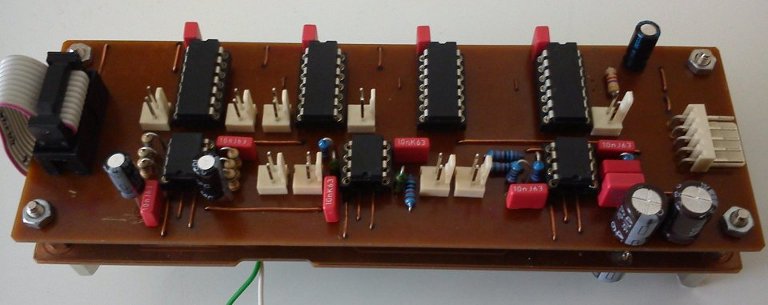
Features
- Four line inputs.
- Two line outputs.
- One sub-woofer line output.
- Volume control.
- Controllable low pass filter for sub-woofer.
- Mixing of the two sources.
- Digital potentiometers MCP42010.
Review
- Input impedance too low due to poor design (summing amplifier directly after input attenuation).
- Distortion at maximum input level.
- No hear-able noise induced by the SPI controlled potentiometers.
- No noise counter-measures needed for SPI (@140kHz).
- The daisy chain configuration for the potentiometers works fine.
- Approx. 35 (logarithmic) volume steps achievable.
- For version two I would spend two PCBs and add a few OPA.
Power amplifier
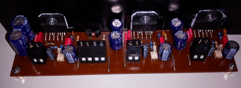
Features
- 3x LM3886T.
- TTL input to control the mute function.
- Almost the same circuit as suggested in the data-sheet.
Review
- Sufficient output power (to wake up the neighbourhood).
- Slight hum noticeable with my DIY 8 Ohm 2-way speakers (ear directly at the speaker).
- No hum noticeable with my old 3-way Grundig Monolith (4-6 Ohm).
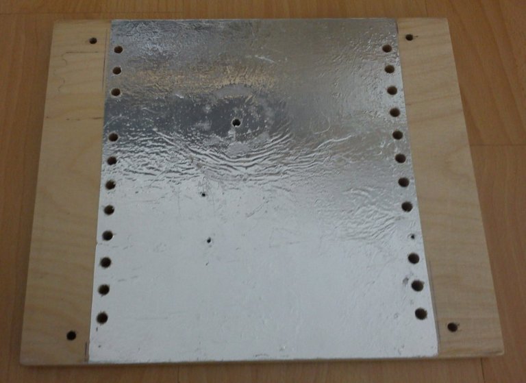
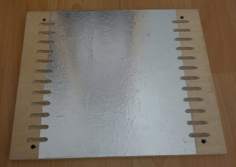
- The hum is induced by the transformer and not a result of poor ground design.
It was reduced with a grounded steel sheet metal (not the optimal material, but available and better than nothing) around the transformer. - Power dissipation even if mute is active.
- Power dissipation at low volume more than expected.
- Output offset voltage between 5mV and 20mV.
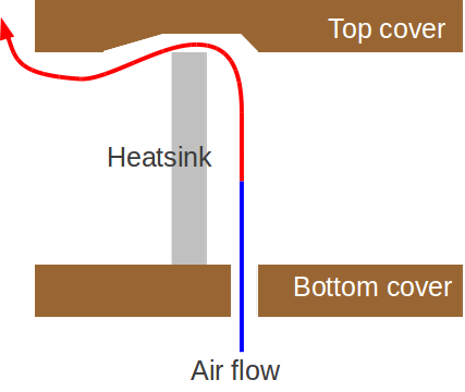
- Heat sink (50x250x40mm, 0.9 K/W) becomes quite warm after a while, but is sufficient.
Headphone amplifier
Features
- Amplifier: 1x OPA2134 (non inverting, gain ~5).
- Only tested with my Sennheiser HD570 (~60 Ohm)
- OPA based meter rectifier to measure the volume level with the micro adc.
Review
- Inserting 5 Ohm resistors at the outputs seem to reduce the low frequency response.
- A version 2 will feature two OPA paralleled.
- The meter rectifier is not working. Error search aborted due to time constraints.
Software
- Software written in C.
- Simple DIY cooperative multitasking os.
- Compiler: GCC
- Program size approx.10k.
Modifications
- Improved cooling
Downloads
- Schematic power supply (PDF)
- Schematic microcontroller board (PDF)
- Schematic power amplifier (PDF)
Publish date: 2012-06-06
Last update: 2012-08-12
![]()
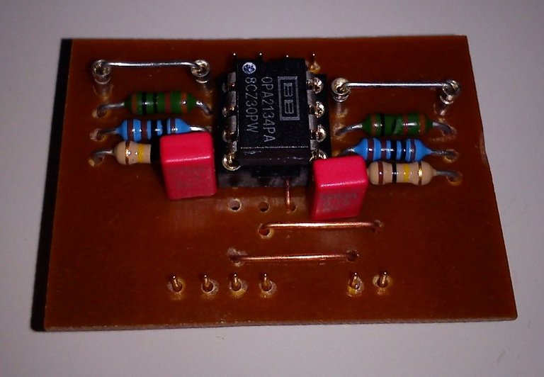
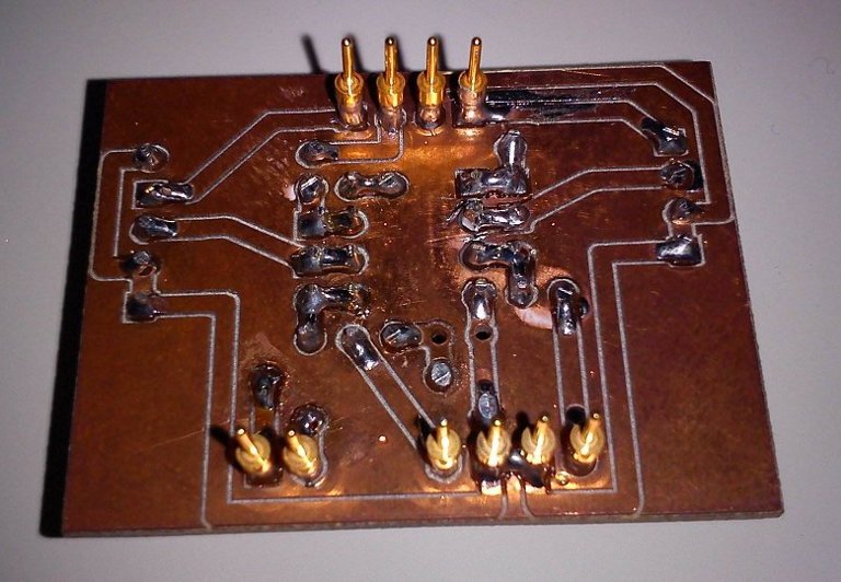
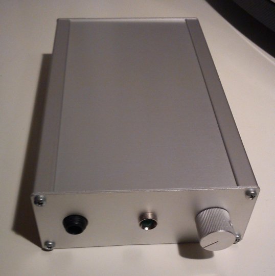
Headphone amplifier
The amp is based on a very simple operational amplifier design.
The main amplifier stage is pluggable to ease the exchange.
The idea was to create a development platform for different amplifier circuits.
I tested the amp with my old Sennheiser HD570 (~60 Ohms) an I am absolutely pleased with the result.
Please note that I am not a Hi-Fi enthusiast.
Download
Publish date: 2012-03-07
![]()
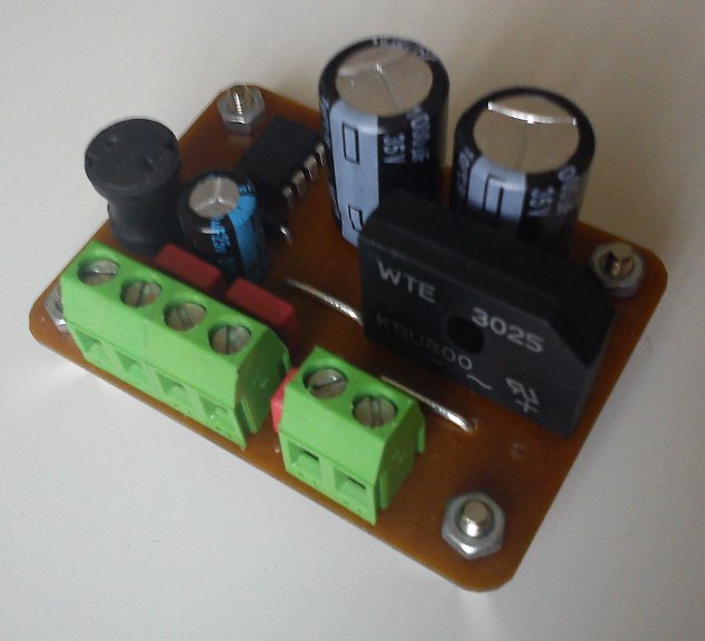
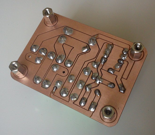
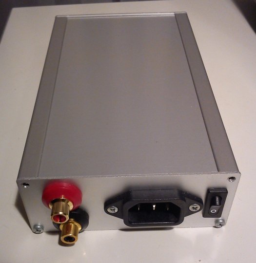
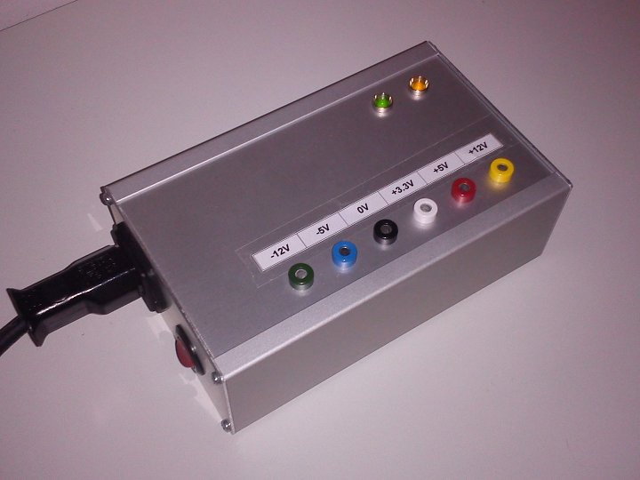
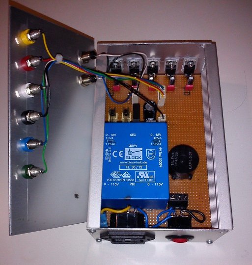
Fixed voltage power supply
A simple power supply with the most common fixed voltages e.g. for testing circuits on a breadboard.
Download
- Schematics (.pdf) (preliminary)
- Bill of materials (.pdf)
Publish date: 2010-06-07
Links
KiCAD - EDA Software suite
Mikrocontroller.net - German forum for micocontroller projects
Renesas Rulz - Forum for Renesas Micros
FreeCAD - Open source parametric 3D CAD modeler
DIY Audio - Forum for audio projects
Visaton - DIY Loudspeakers
Last update: 2013-10-31